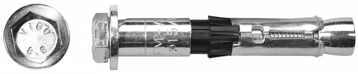
R-SPL-II-L SafetyPlus II - Loose Bolt
High performance mechanical anchor - loose bolt option


Features and benefits
- Mechanical anchor for highest tension and shear loads
- Seismic category C2 for structural applications. Seismic category C1 for non-structural use in areas with low seismic risk.
- For usage with required fire resistance
- ETA Option 1 for cracked and non-cracked concrete.
- Antirotation brush to prevent rotation during installation.
- Anchor's construction allows easy through-installation (drilling and installation through fixed material)
- Three types of tips (nut, flat or tapered bolt) allow simple fitment for installed element
- 8.8 grade steel material of anchor provides high durability
Product information
Size |
Product Code |
Anchor |
Fixture |
|||
Thread size |
External diameter |
Length |
Max. thickness |
Hole diameter |
||
d |
dnom |
L |
tfix |
df |
||
[mm] |
[mm] |
[mm] |
[mm] |
[mm] |
||
M6 |
R-SPL-II-06080/20L |
6 |
10 |
80 |
20 |
12 |
R-SPL-II-06110/50L |
6 |
10 |
110 |
50 |
12 |
|
M8 |
R-SPL-II-08080/10L |
8 |
12 |
80 |
10 |
14 |
R-SPL-II-08090/20L |
8 |
12 |
90 |
20 |
14 |
|
R-SPL-II-08120/50L |
8 |
12 |
120 |
50 |
14 |
|
M10 |
R-SPL-II-10090/10L |
10 |
15 |
90 |
10 |
17 |
R-SPL-II-10100/20L |
10 |
15 |
100 |
20 |
17 |
|
R-SPL-II-10130/50L |
10 |
15 |
130 |
50 |
17 |
|
R-SPL-II-10180100L |
10 |
15 |
180 |
100 |
17 |
|
M12 |
R-SPL-II-12110/10L |
12 |
18 |
110 |
10 |
20 |
R-SPL-II-12125/25L |
12 |
18 |
125 |
25 |
20 |
|
R-SPL-II-12150/50L |
12 |
18 |
150 |
50 |
20 |
|
R-SPL-II-12200100L |
12 |
18 |
200 |
100 |
20 |
|
M16 |
R-SPL-II-16125/10L |
16 |
24 |
125 |
10 |
26 |
R-SPL-II-16140/25L |
16 |
24 |
140 |
25 |
26 |
|
R-SPL-II-16165/50L |
16 |
24 |
165 |
50 |
26 |
|
R-SPL-II-16215100L |
16 |
24 |
215 |
100 |
26 |
|
Base material
-

Cracked concrete C20/25-C50/60
-

Non-cracked concrete C20/25-C50/60
-
Unreinforced concrete
-
Reinforced concrete
For use also with
-

Natural Stone (after site testing)
Applications
- Structural steel
- Masonry support
- Cladding restraints
- Road Signs
- Heavy machinery
- Racking systems
- Industrial doors
- Safety barriers
Installation guide
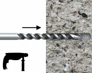
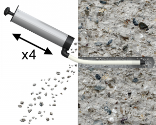
- Drill a hole of required diameter and depth
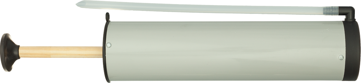
- Clear the hole of drilling dust and debris (using blowpump or equivalent method)
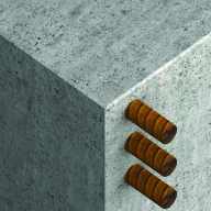
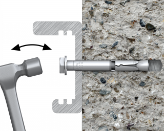
- Insert anchor through fixture into hole and tap until required installation depth is achieved
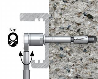
- Tighten to the recommended torque
Installation data
Size |
M6 |
M8 |
M10 |
M12 |
M16 |
||
Thread diameter |
d |
[mm] |
6 |
8 |
10 |
12 |
16 |
Hole diameter in substrate |
d0 |
[mm] |
10 |
12 |
15 |
18 |
24 |
Hole diameter in fixture |
df |
[mm] |
12 |
14 |
17 |
20 |
26 |
Installation torque |
Tinst |
[Nm] |
10 |
20 |
45 |
80 |
150 |
Wrench size |
Sw |
[mm] |
10 |
13 |
17 |
19 |
24 |
Min. hole depth in substrate |
h0 |
[mm] |
75 |
85 |
95 |
115 |
130 |
Min. installation depth |
hnom |
[mm] |
60 |
70 |
80 |
100 |
115 |
Min. substrate thickness |
hmin |
[mm] |
100 |
120 |
140 |
180 |
200 |
Min. spacing |
smin |
[mm] |
50 |
60 |
70 |
80 |
100 |
Min. edge distance |
cmin |
[mm] |
50 |
60 |
70 |
80 |
100 |